
Overhead line engineering · Digital solutions
From as-built drawings to a verified asset record.
LYNTRX reads tram and trolleybus overhead line drawings, checks them against the operator's own standards and produces a 3D component model, cable analysis and installation documents. Everything is provided through a project portal – from one source and updated together.
From plans to a connected tomorrow
Starting point
The asset record sits in the drawing archive – not yet in a model.
Every tram and trolleybus operator keeps its overhead contact line in 2D drawings. They are to scale, dense with detail and maintained over decades. They are simply not data.
Renewal, maintenance, abnormal transport clearances and BIM deliverables all call for data that can be checked: where each pole stands, which type it is, what is attached to it, which forces act on it, how high the contact wire runs. That information is in the drawing – spread across pole stamps, annotations, layers and blocks, written in each operator's own conventions.
Re-surveying a network is expensive and slow. Transferring it by hand is slow too – and only as reliable as the attention paid at every single support.
Two building blocks, one data set
LYNTRX3D creates the record. LYNTRX360 keeps it alive.
Both work on the same asset data set. When the installation changes, the record is updated rather than re-collected – and every document is produced again together.
Capture, calculate, model
The extension for Autodesk Civil 3D interprets the drawing set, checks the data against itself and builds the 3D component model, the cable analysis and every document from it.
Explore LYNTRX3DShow, review, keep current
Platform and app for everyone working with the result: documents per project and per support, findings with a drawing extract, 3D in the browser, feedback from the field.
Explore LYNTRX360What you get
One data set – and everything that follows from it.
Model, analysis, checks and documents are not produced one after another by hand. They are generated together from the same state. That is the difference between a model and an asset record.
Asset register per support
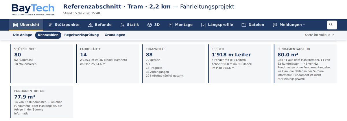
Pole type, length, foundation, cantilever, attachments and tensile forces – as a table, in the model and on a page of its own for each support.
3D component model in terrain
Poles, foundations, cables, clamps, insulators and wires as components with properties – on the swisstopo terrain model, in Swiss national coordinates.
Cable analysis per structure
Cable geometry, end forces and loads from the attachments, for normal and exceptional load cases, compared with the values stated in the drawing.
Cross-checks and findings
Contact wire height, stagger, span length, attachment angle and cable shape checked against the operator's standards – each finding with drawing extract, measured value and limit.
Installation sequence with QR codes
One sheet per structure and per conductor, with a 3D view and installation status. Every support carries a QR code leading to its page on a tablet.
Cross and longitudinal profiles
Longitudinal profile per contact wire and feeder with road surface, heights and attachments; cross profiles at the structures.
Bills of quantities
Components and assemblies counted against the operator's catalogue – every quantity with the rule that produced it.
IFC 4.3 and open formats
The model as IFC 4.3 with component properties and materials, plus 3D DWG, KMZ and tables. No licence required to carry the data forward.
Approach
Four steps, one source.
The first step is done once per operator. Every further section of the same network starts at step 2.
Interpret the drawing set
Layers, blocks, pole stamps and annotations are read and their meaning verified against the operator's standards – once per drawing convention, not per drawing.
Check the data set
Supports, wires, cables and components are extracted and calculated against each other. Whatever fails a cross-check is reported – not believed.
Model and documents
The data set yields the 3D model, cable analysis, installation sequence, profiles, bills of quantities and registers – together, from one state.
Portal and updating
Everything on the project page, with feedback per entry. After a rebuild the record is updated instead of collected again.
Have a section of your own calculated?
One to two kilometres are enough to start. What is needed are the drawings as a CAD file and the operator's standards – pole and foundation tables, nominal heights, assembly documentation.