
LYNTRX3D · Capture and calculation
The extension that turns a drawing into a record.
LYNTRX3D is a plugin for Autodesk Civil 3D. It reads the drawing set, checks the data against itself and against the operator's rulebook, and produces model, analysis and documents – in a single run.
What it does
Eight tasks, one run.
What used to be done one after another by hand – reading, drawing, calculating, checking, documenting – runs as a chain and ends with a complete, consistent state.
Read the drawing set
Layers, blocks, pole stamps, annotations and dimensions are read according to the operator profile. Supports, structures, wires, cables, attachments and special components form one connected data set.
Establish topology
Which cable hangs on which anchor, which wire crosses which, where the ring sits, where the fork: the connections are derived from the geometry and checked for consistency.
Derive heights
Annotated heights take precedence. Where none is given, the operator's rule applies – nominal height, system height, base gradient – and the data set records that the height was derived.
Run cross-checks
Contact wire height, stagger, span length, gradient, clearances to buildings and vegetation, utilisation of the supports – against limits stored in the operator profile with their source.
Build the 3D model
Poles from the type catalogue, foundations, cantilevers, chains, clamps, insulators and cables as solids with properties – on the terrain model and between the buildings.
Recalculate cable statics
Cable polygon with point loads per structure, load cases for temperature, wind and additional load, end forces, resultant and moment per pole, deflection check.
Generate documents
Project report, analysis sheets, installation sequence, cross and longitudinal profiles, drawing sheets, registers and bills of quantities – all from the same state.
Write the handover
IFC 4.3, 3D DWG, KMZ, tables and PDF, arranged in a delivery folder and uploaded to the portal on request.
Operator profile
The numbers belong to the operator, not to the program.
A limit value written into a program is a claim. A limit value held in the operator's profile – with severity, source and remark – is a traceable decision.
LYNTRX3D therefore carries no standard values of its own. Nominal heights, permissible stagger, span lengths, clearances and load capacities come from the rulebook of the operator concerned. If a value is missing, the rule is not checked – and the report says so, rather than inventing a number.
Checked among other things:
- Contact wire height within the track area, lowest and highest
- Longitudinal gradient and change of gradient at the support
- Span length between load-bearing supports
- Stagger against the track axis
- Clearance of live parts to buildings and vegetation
- Utilisation of pole, wall anchor and cable cross-section
- Required height on abnormal transport routes, including sag
Cable analysis
Not just drawn – recalculated.
A model shows what it looks like. Only the analysis shows whether it holds.
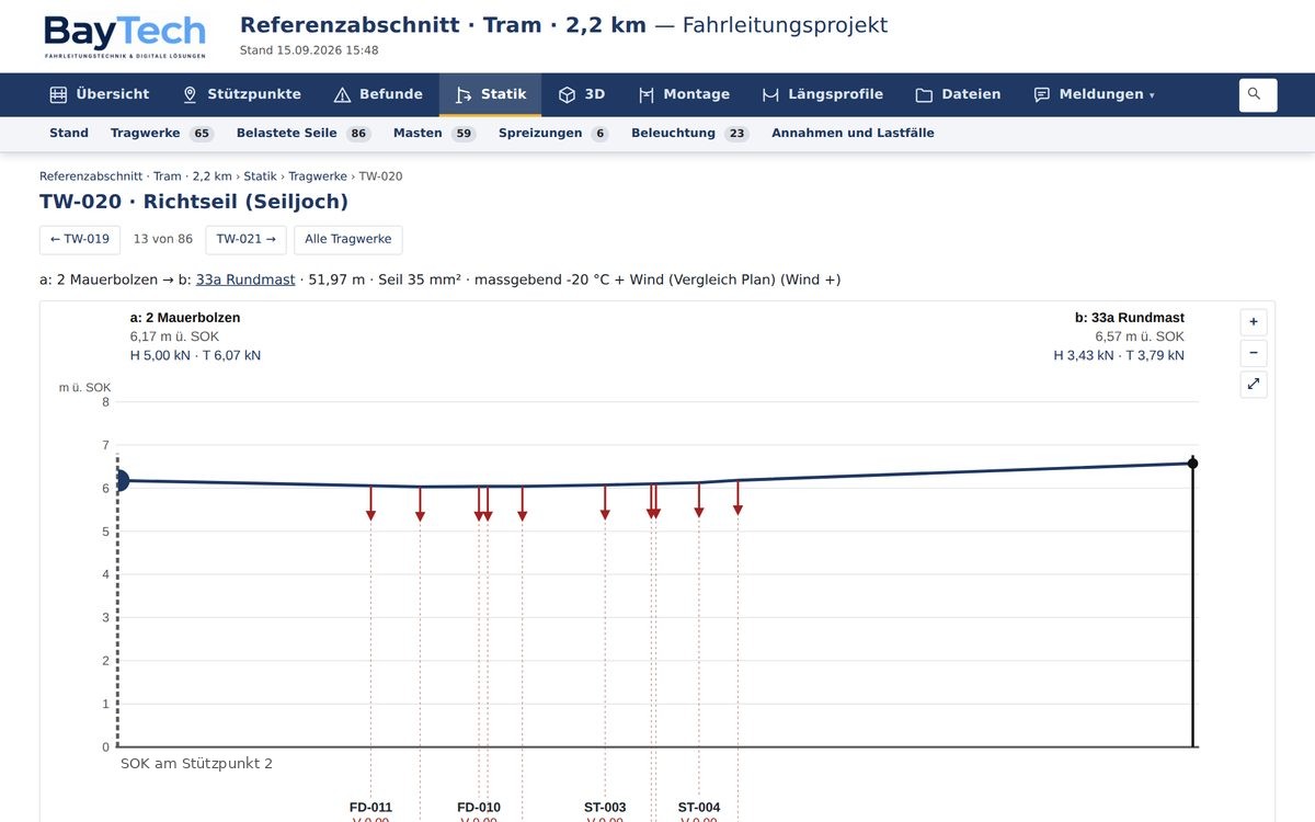
Every cross-span, every support cable and every anchor is calculated as a cable polygon with point loads: self-weight of the conductors, weight of the attachments, radial forces from the wire deflection.
Several load cases are calculated – temperature, wind, additional load – and dimensioning is done for the normal case, while pole design uses the governing one. For each pole the resultant, the moment about the foundation top and the deflection check are produced.
- Load cases per the governing rulebook, with named assumptions
- Comparison with the force values in the drawing where available
- Assessment against fixed criteria – cable, wall anchor, pole, shape, deflection
- Remedy stated: how much sag or height is missing when a value does not hold
Component model
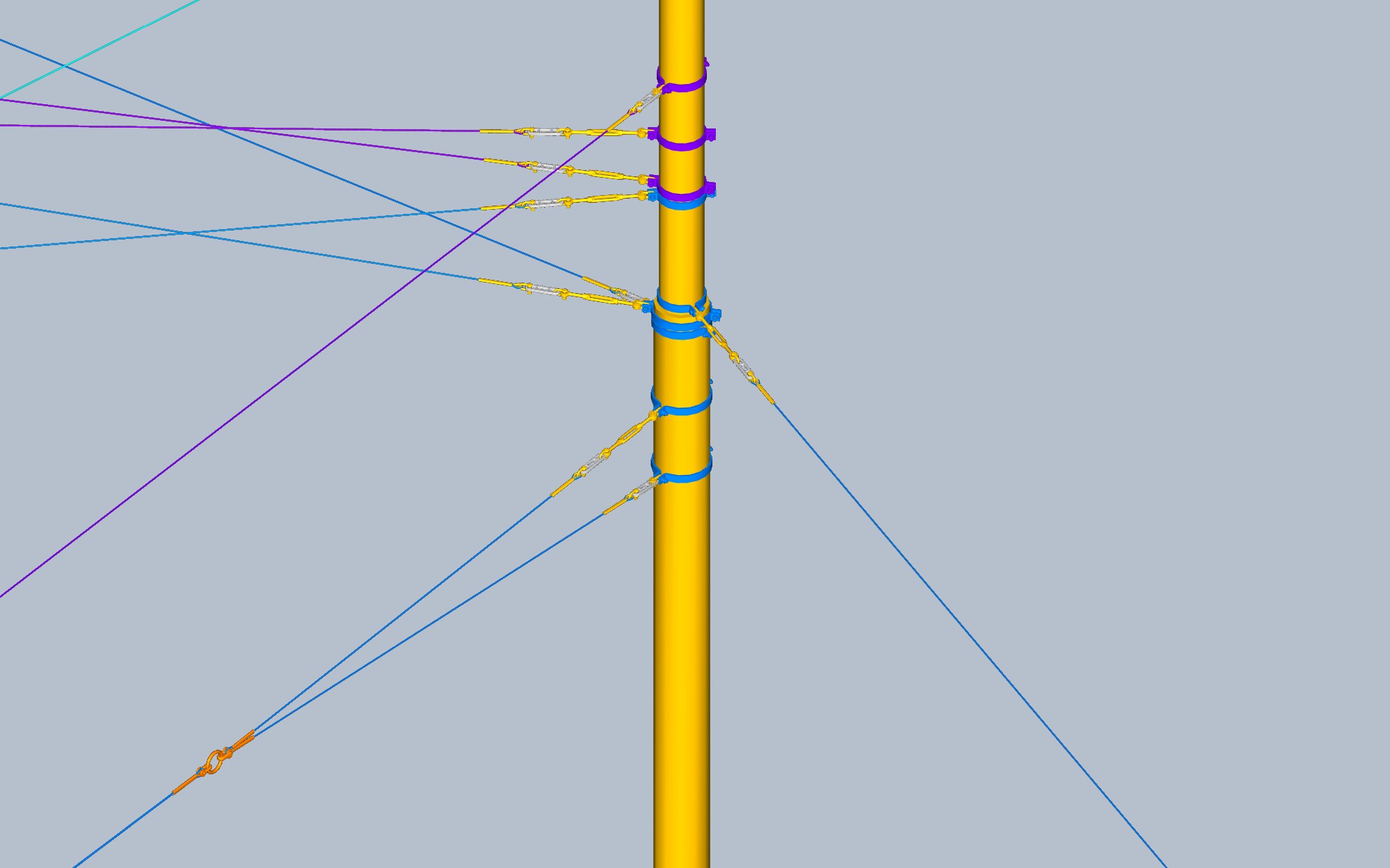
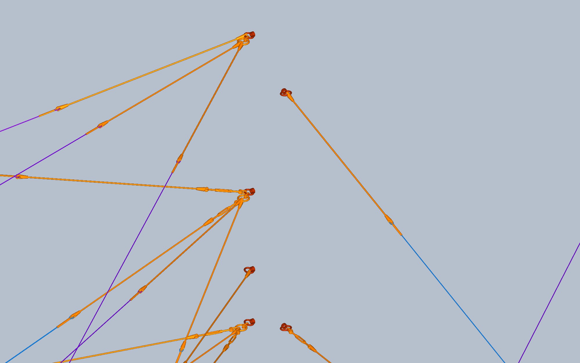
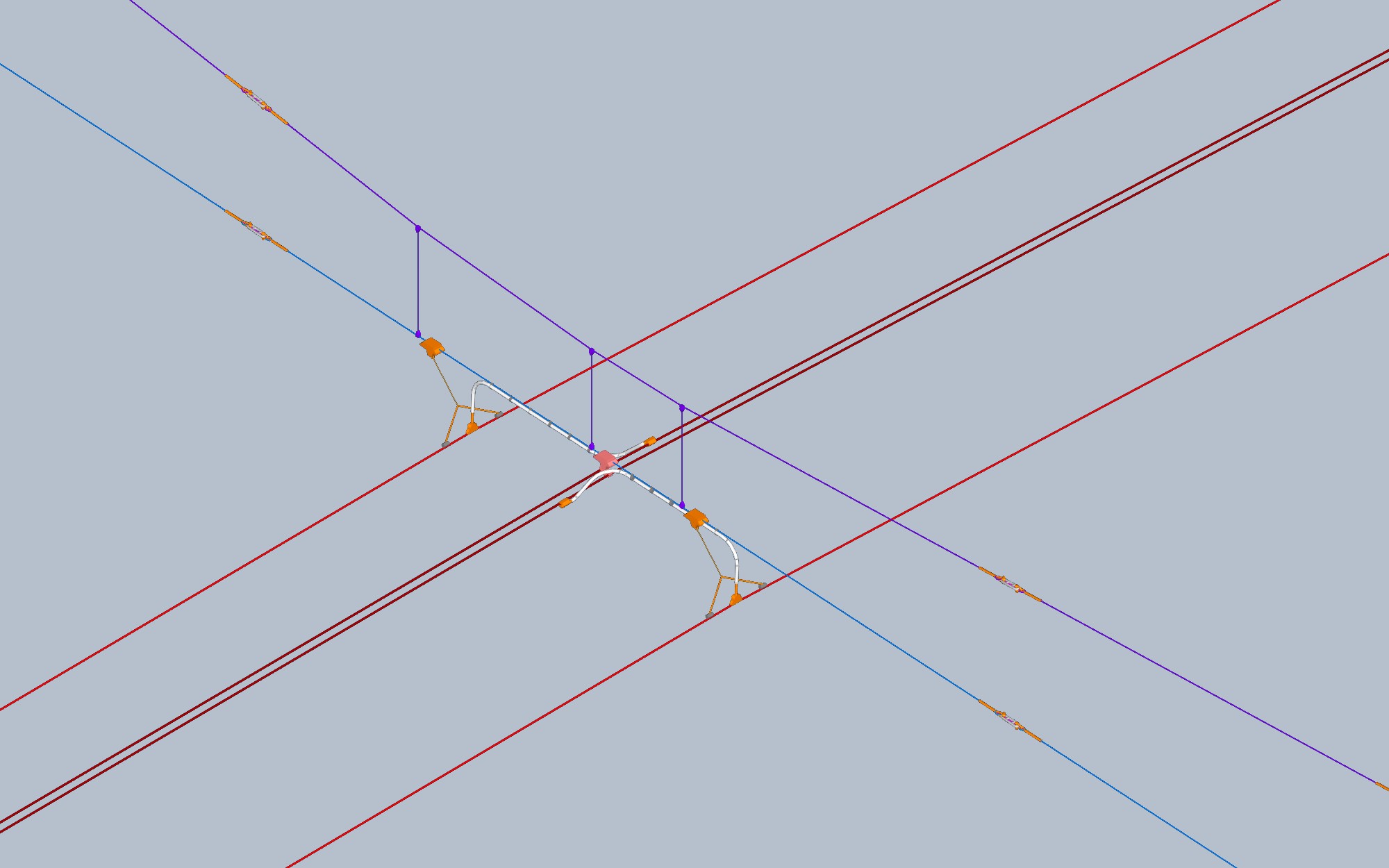
What gets installed is in the model.
Not a line network with symbols, but components from the operator's catalogue – with part number, material and position.
Technology
What it builds on.
Environment
Terrain from swissALTI3D, buildings from swissBUILDINGS3D, land cover from the official cadastral survey, abnormal transport routes from the harmonised geodata set. National coordinates LV95, heights LN02. Outside Switzerland we rely on the official data of the respective country – such as terrain models and 3D buildings from the German federal states or Austria's BEV – in the coordinate and height system used there. Where such data is unavailable or the operator keeps its own survey data, we work with that.
Components
Poles, foundations, chains, clamps, insulators and attachments as solids with article number, material and weight – following the operator's component catalogue.
Platform
Autodesk Civil 3D as the working environment, processing chain in Python, model checking via Navisworks. The result is open – IFC 4.3, DWG, tables, PDF.
Try LYNTRX3D on your own drawings.
The first section shows how much your drawing stock yields – and where it has gaps that are worth knowing about anyway.